Everything You Need To Know About Light Wiring Wiring Lights Diagram
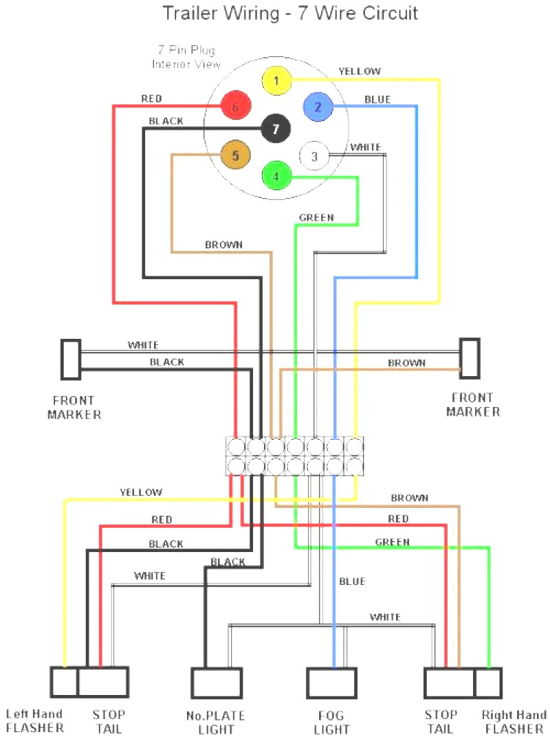
Trailer Lights Wiring Diagram Cadician's Blog
1 Cut power to your circuit. [1] The best way to do this is by turning off the electricity supplied to the circuit on which you will be working at the junction box (also called a fuse box) for your home. Switch the breaker of your fuse-box so the fuse for the circuit supplying electricity to your fixture reads "Off." [2]
Two Light Trailer Wiring Diagram Lights Collection
This 3-way light switch wiring diagram shows how to wire the switch and the light when power is coming to the light fixture. In this diagram, power enters the fixture box. The black hot wire connects to the far right switch's common terminal. Red and blue wires link the traveler terminals of both switches. The red wire, which is connected to.
Electrical and Electronics Engineering Wiring diagrams for lights with
An intermediate lighting circuit is used when one circuit is to be turned on or off by three or more switches. The single circuit may have one or more lights in it. This type of circuit uses two of the two way switches and one or more of the intermediate switches. A wiring and circuit diagram is shown below. Intermediate lighting wiring diagram.

Citroen Speakers Wiring Diagram
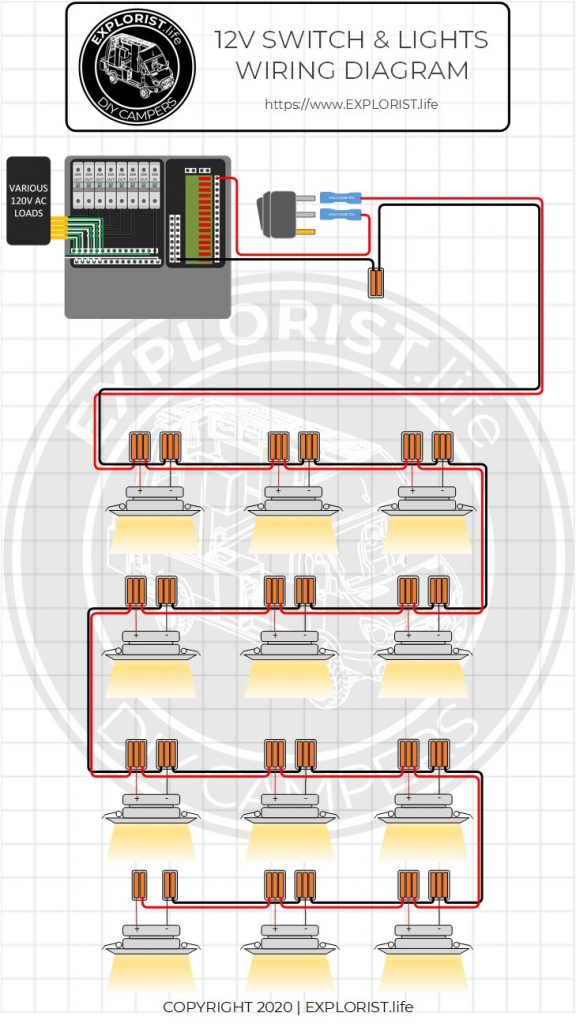
To wire a series of lights, connect the positive end of one light to the negative end of the next light. Wiring lights in series means that all the lights in the circuit are connected along the same wiring path. This is a simple and cost-effective way to connect multiple lights, such as in a hallway or along a fence line.

Electrical Wiring Diagram Led Lights Headlights Eminem Ava Schema
A lighting wiring diagram is a visual representation of the electrical wiring in a room or home. It displays the layout of the electrical components as they are connected including light switches, outlets, light fixtures, conduits, and junction boxes.

Wiring Diagram For Auxiliary Reverse Lights
In Australia, the main method used to wire lights is called the 'loop at the light' method. How does this method work? The loop at the light method works by using batten and rose light mountings to create extra blank terminals which are used to join the loop wires.

Wiring Diagram For Recessed Lights In Parallel
Ceiling rose wiring diagrams are useful to help understand how modern lighting circuits are wired. All electrical pages are for information only! New rules have been introduced for electrical safety in the home, please read this document by clicking here, before starting any electrical work

Wiring Diagram For Kings Driving Lights
They require three phase wiring, or multiphase, to meet extra demand. As per current Australian electrical standards, single phase wiring colours are: Active - Brown. Neutral - Blue. Earth - Green & Yellow. Meanwhile, Australian three phase wiring is: Phase 1 - Brown. Phase 2 - Black. Phase 3 - Grey.
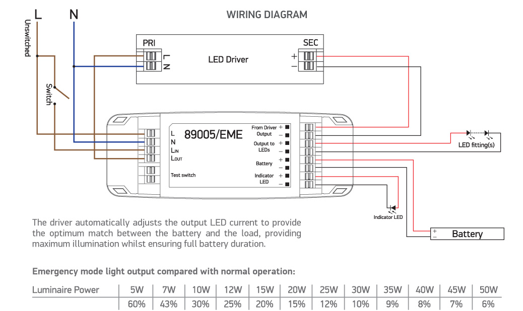
Emergency Lights Wiring Diagram Collection
How to Wire a Light Switch in Australia: The Steps. Power off: Safety first! Always ensure the main power source is disconnected before attempting any electrical work. Remove switchplate/assembly: Carefully remove the existing switchplate or assembly to expose the wires. Check wires: Examine the wires to ensure they are in good condition and.

Car Spotlight Wiring Diagram Uk
February 22, 2023 Electrical LiVE Services Group How To Wire A Light Switch In Australia Table of Contents Types Of Light Switches Used In Australia How To Select The Right Light Switch Tool Requirements For The Wiring Step-By-Step Guide To Installing A Standard Light Switch Step-By-Step Guide To Installing A Two-Way Switch

Wiring Diagram For Trailer Lights Nz 2nd Gen 4x4 Kye Wired
Find the deal you deserve on eBay. Discover discounts from sellers across the globe. Try the eBay way-getting what you want doesn't have to be a splurge. Browse Wire schematic!

Wiring Diagram For Outside Lights
Step 3: Connect a new cable. If you're wiring a new switch from scratch, then you can skip the above process. Instead, find a suitable point along the cable connecting your light and the power source. Measure and install the conduit pipe accordingly, then slide the cable into it.

House wiring diagram. Most commonly used diagrams for home wiring in
A wiring diagram is a simplified representation of the conductors (wires) and components (devices, lights, motors, switches, sensors and more) that make up an electrical circuit or electrical system. Some wiring diagrams show the exact wire connections that must be made for the system to work, while others offer a graphical representation of how electricity flows through a circuit.

Wiring Diagram Marvelous Lights In Series Or Parallel For Downlights
1 And you forgot to check how it was connected to the old lamp.. oops :) Loop can either mean it needs to be connected to A because it goes to another loop switch or connected to N because it acts like ground loop. You need a multimeter to verify where the cable goes. We cannot answer that question with certainty. - Piotr Kula Aug 15, 2012 at 15:44

Simple Wiring Diagram For Light Bar
This diagram illustrates wiring for one switch to control 2 or more lights. The source is at SW1 and 2-wire cable runs from there to the fixtures. The hot and neutral terminals on each fixture are spliced with a pigtail to the circuit wires which then continue on to the next light.

Wiring Diagram For Underglow Lights
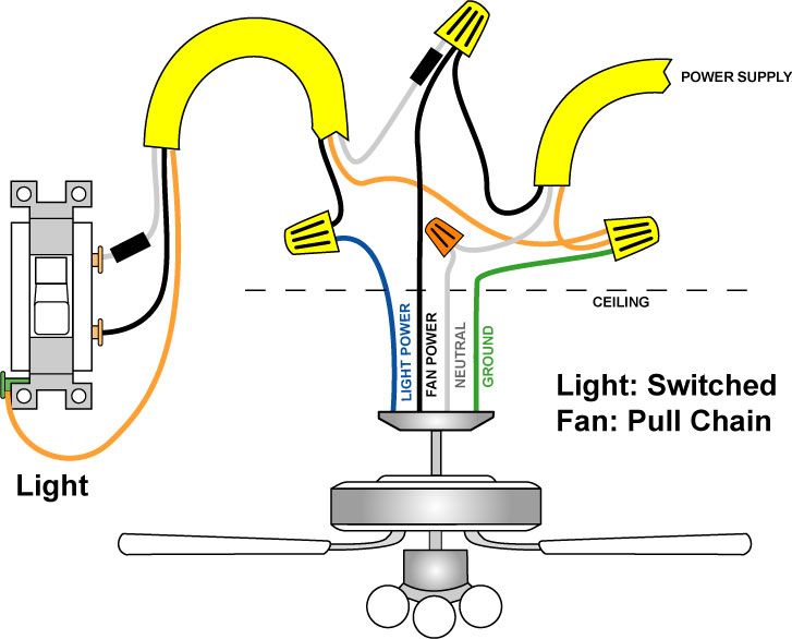
Wiring Your Home: How to Wire Light Fixtures. Part of the series: Home Improvements: Bath, Electric and Around the House. Wiring light fixtures in your home.
